How a Press-Fit or a Joint Clearance Differs from Kerf Compensation
Kerf compensation offsets the toolpath to hold drawing size. Joint clearance is a second number for how tight a tab and hole sit after the cut.
On a wood, acrylic, or metal sheet, the cutter still consumes a slot. Kerf compensation only moves the laser, waterjet, plasma, or saw so that slot sits on the scrap side of the drawn line and the finished hole and tab match the drawing. The tightness of that hole-and-tab pair after assembly is a second number; it is not the slot and it is not the offset. Before the nest or the quote, measure the slot on a coupon, keep the joint on its own line, and do not merge the two.
Answer box
| What is being counted | The gap or overlap between a finished hole (an internal feature of size) and a finished tab or pin (an external feature of size) after both have been cut. ISO 286-1:2010 names that relationship a fit, and names the positive difference a clearance and the negative difference an interference. Opened 29 September 2026. |
|---|---|
| What is not being counted | The strip the beam, jet, or blade removes, and the half-width offset that CAM uses to keep the cutter off the finished face. Autodesk Fabrication states that kerf is the tool width and that the path is offset by half of that width. Opened 29 September 2026. |
| The measurement that decides it | The actual size of the hole against the actual size of the tab, both taken after the cut. ISO 286-1:2010 defines actual size as a measured size and requires the two features that form a fit to share the same nominal size before deviations are applied. Opened 29 September 2026. |
| What a catalog figure leaves out | A software field for kerf correction is an input range, not a press-fit. Trotec Ruby 2.10, for Speedy machines, accepts kerf correction from 0.05 mm to 20 mm (0.002 in to 0.394 in). That range does not name a material, a thickness, or a joint. Opened 29 September 2026. |
| Check before the batch or the quote | Record material, thickness, process, and machine next to the measured slot. Leave the joint clearance or interference on the drawing as its own deviation. Do not add it into the kerf offset. |
| Last checked | 29 September 2026 |
What the slot removes on a hole and a tab
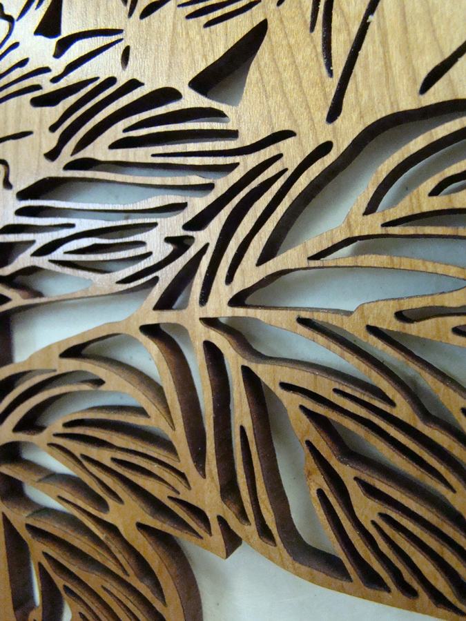
A laser vaporizes or melts a narrow path. A waterjet erodes a path with a high-pressure stream. A plasma arc severs conductive sheet with ionized gas. A saw leaves a toothed slot. In every case the missing strip is the kerf. It is not the finished width of the tab, and it is not the finished width of the hole.
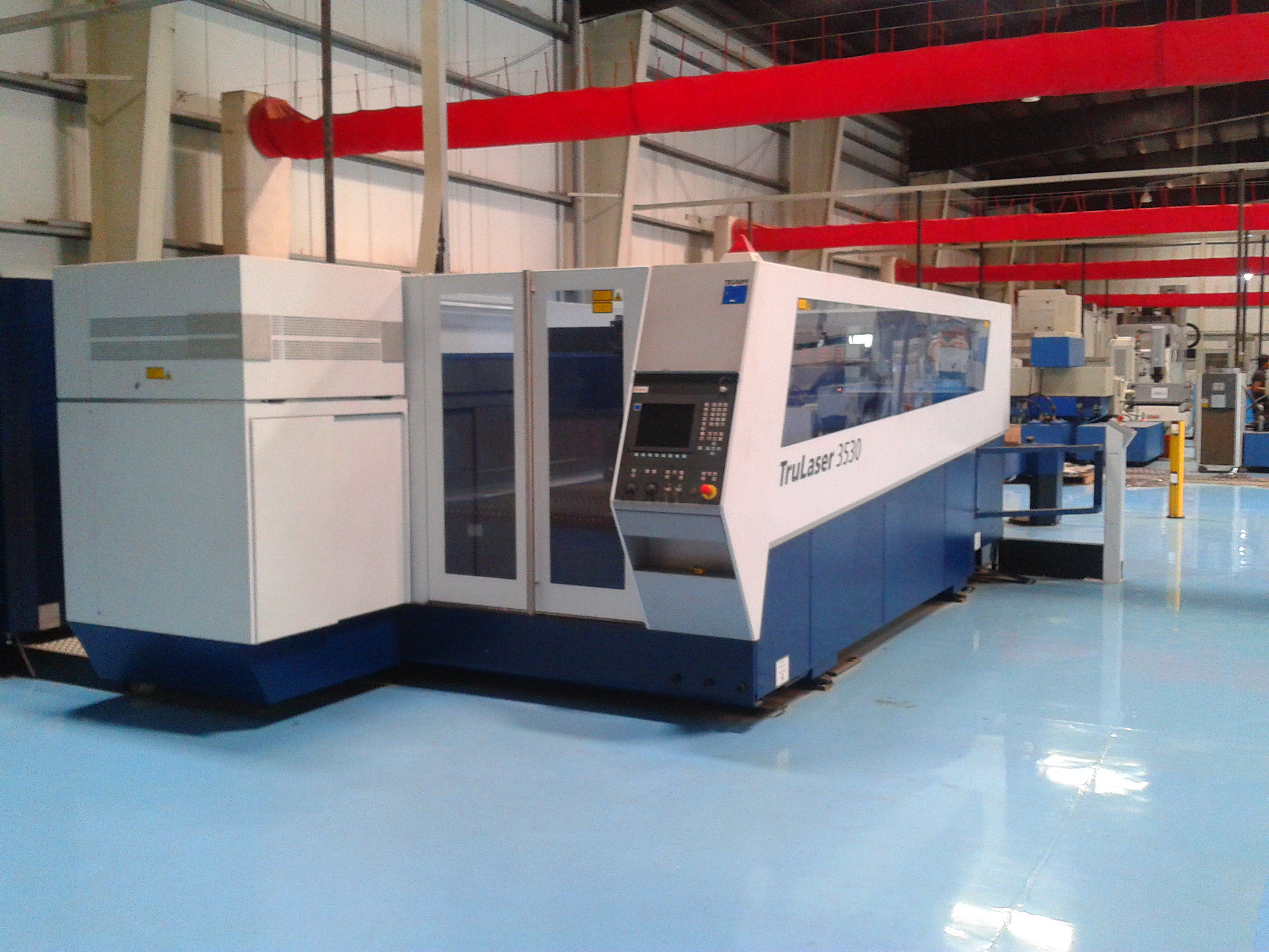
Trotec’s vector-processing notes for Ruby state that the laser cuts in the middle of the drawn line. If the drawn line is the finished outline and the head stays on that line, the outside of a tab loses stock on both sides and comes out small, and the inside of a hole loses stock on both sides and comes out large. Autodesk Fusion’s 2D Profile reference puts the same fact in CAM language: a Center compensation setting places the cutting head on the selected edge; an Etch mode uses that centerline and applies no cutter-width compensation. Through-cuts are the jobs that need the offset.
The parts a reader can point to on the table are the nozzle or the lens, the sheet edge, the skeleton left in the plate, and the slug that drops from a hole. Autodesk Fabrication’s kerf note says that if the skeleton in the plate is measured, that leftover equals the part size plus twice the kerf. That leftover is still kerf loss. It does not describe how tightly the tab will sit in the hole after both pieces leave the nest.

Why the same offset is not the joint
Kerf compensation moves the toolpath. It does not redraw the finished part. Autodesk Fusion’s 2D Profile type “In computer” calculates the head position from the kerf diameter and the sideways direction, then writes the compensated coordinates. “In control” writes the selected chain and leaves the offset for the machine. Autodesk Fabrication states the same geometry another way: the tool is offset by half the kerf, and the direction of that offset depends on whether the contour is an inside hole or the outside of a part. None of those pages is a fit table.
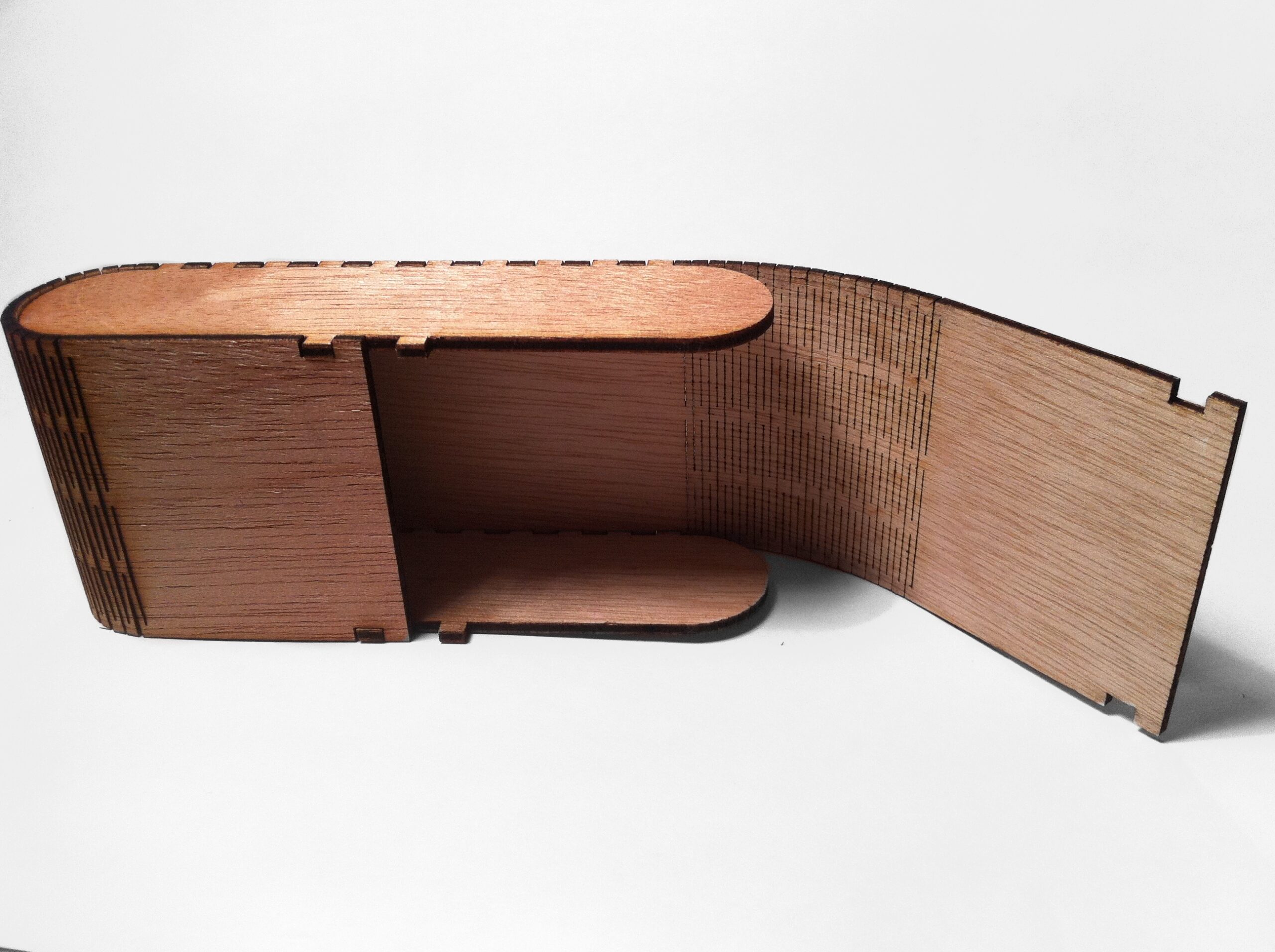
ISO 286-1:2010 is. It defines clearance as the difference between hole size and shaft size when the shaft is smaller, and interference as the difference before mating when the shaft is larger. A clearance fit always leaves a gap. An interference fit always leaves an overlap. A transition fit can land on either side, depending on the actual sizes. The standard uses “hole” for an internal feature of size, including non-cylinders, and “shaft” for an external feature of size, including non-cylinders. The introduction states that those terms also cover two parallel opposite surfaces, such as the thickness of a key or the width of a slot. A rectangular tab in a rectangular opening is that case. The same introduction requires the two features that form a fit to share one nominal size. Deviations from that nominal then create the gap or the overlap. Kerf compensation is how the cutter is told to land on those finished sizes. The fit is how those finished sizes are supposed to sit together.
That split fails differently from a later bend or a later machining pass. Extra stock for a bend, a mill, or a grind is allowance on the blank that the cutter has not yet removed and that kerf compensation does not supply. A press-fit or a sliding clearance is not extra stock on the blank. It is a change to the finished hole, the finished tab, or both, relative to the shared nominal, after the slot has already been taken. Folding either number into the kerf offset hides the line the next operation or the next assembly actually needs.
ASME B4.1-1967 (R2020) covers the same idea for plain, non-threaded cylindrical parts: it presents definitions of fits and recommended allowances, tolerances, and fits for diameters up to 20 inches. It is a standards page for the joint, not a kerf listing for a laser, a waterjet, or a saw. It does not replace a coupon cut on this sheet.

What to check on the standard, the coupon, and the first pair
Open ISO 286-1:2010 on the ISO catalogue page for standard 45975, or ASME B4.1-1967 (R2020) on the ASME product page. Both were opened on 29 September 2026. ISO 286-1:2010 remains current; the catalogue entry states it was confirmed in 2026. Look for the shared nominal, then for the limit deviations on the hole and on the tab. Do not look there for a kerf width. Autodesk Fusion’s 2D Profile reference (opened the same day) shows whether compensation is calculated from a kerf diameter in the program or left for the control. Trotec’s Ruby vector-processing page (opened the same day) shows whether a Speedy job is still cutting on the center of the line or has had an inset or an outset applied. Those pages name the path offset. They do not name the joint.
Cut a coupon in the same material, thickness, and machine as the job. Measure the slot. Record those four facts next to the width. If one is missing, leave the kerf field blank. Trotec Ruby 2.10’s 0.05 mm to 20 mm correction window is a legal input on Speedy machines; it is not a measured slot in plywood, acrylic, or steel.
On the first pair, use a caliper on the finished hole and on the finished tab, not only on the slot. ISO 286-1:2010 calls that measured size the actual size. Compare the pair against the clearance or interference the drawing named. If the slot was wrong, the path offset is the first suspect. If the slot was right and the pair is still loose or locked, the joint number was wrong or it was baked into the offset.
The decision before the nest or the quote
Leave the kerf width blank until the coupon has the four facts. Set compensation so an outside profile does not shrink below the drawing and an inside profile does not grow past it. Then set the joint as a separate deviation on the hole, the tab, or both.
Do not publish one press-fit size for acrylic, plywood, or any other material, and do not copy one into the nest. Sheet name is not enough. Thickness changes the slot even when the name stays the same, and the joint still has to be stated for that pair. If the drawing has no clearance and no interference, the quote cannot promise a press-fit. If the drawing has a fit and the CAM file has only a single offset, the batch will hit the drawing size or the joint, not both, unless those two numbers were already identical by accident.
Autodesk Fusion’s 2D Profile overview ranks laser, waterjet, and plasma by kerf in qualitative terms only: laser smallest, waterjet moderate, plasma largest. That ranking is about the slot and the edge, not about which process wins a joint. A process can hold the drawing size and still deliver the wrong tightness if the second number was never entered.
One fact that belongs to the fit, not the cutter
ISO 286-1:2010, clause 3.3.3, defines a fit as the relationship between an external feature of size and an internal feature of size that are to be assembled. Clause 3.3.1 treats clearance as positive when the shaft is smaller than the hole. Clause 3.3.2 treats interference as the case when the shaft is larger, with those values negative in the calculation notes. Nothing in those clauses is a laser wattage, a waterjet pressure, or a blade thickness. Trotec’s industrial cutter page states that the beam achieves “minimal kerf” and lists a smallest radius of 1/10 mm; that is a path claim, not a tab clearance. Autodesk Fabrication states that thermal-cutting kerf is normally material and gauge dependent and belongs in the machine-tool database for each material and thickness. That is the cut number’s home. It is still not the fit.
.jpg)
The mistake that ships the wrong tightness
The harmful move is to add the joint into the kerf offset and then treat the drawing outline as finished. On an outside tab the slot already makes the part smaller; extra inset for a “press-fit” can lock parts that the drawing only wanted to locate. On an inside hole the slot already makes the opening larger; extra outset for a “clearance” can leave a sloppy pair that the drawing wanted tight. Because ISO 286-1:2010 requires a shared nominal before the deviations that create the fit, hiding those deviations inside a path offset erases the only size the caliper can check against the drawing. The coupon then looks fine, the nest looks full, and the first assembled pair is the first place the error shows. Keep the slot on the CAM side. Keep the gap or the overlap on the drawing. Measure both before the batch.
Read next: What kerf compensation changes on the toolpath, and what it leaves untouched on the drawing · What extra material a later bend or machining pass still needs