What kerf compensation changes on the toolpath
Kerf compensation offsets the toolpath so the slot sits in the waste. The drawing stays unchanged. Check the first part with a caliper.
Kerf compensation moves the cutter so the slot falls in the waste, not through the finished edge. On sheet metal, plywood, acrylic, or a waterjet plate, the drawing still shows the part you mean to ship. Before a batch or a quote, offset the toolpath once from a measured slot, then check the first outside size and the first opening with a caliper against that drawing.
Answer box
| What is being counted | The strip the cutter still removes after the toolpath has been offset from the drawn edge. OMAX GlobalMAX help calls that strip the kerf (opened 29 September 2026). |
|---|---|
| What is not being counted | The finished outline on the drawing, a later bend or mill allowance on the blank, or the tightness a joint needs after the slot is already cut. |
| The measurement that decides it | A caliper reading on the first part, compared with the drawing, plus a coupon slot cut in the same material, thickness, process, and machine. OMAX states the tool offset to enter is half that measured kerf width (opened 29 September 2026). |
| What a catalog figure leaves out | A mixing-tube bore, a blade listing marked “kerf,” or a nozzle size. Those are maker figures for the consumable, not the slot in this sheet on this machine. |
| Check before the batch or the quote | Measure one outside profile and one inside opening on the first piece. If either disagrees with the drawing, find whether the offset was skipped, doubled, or taken from a catalog instead of a coupon. |
| Last checked | 29 September 2026 |
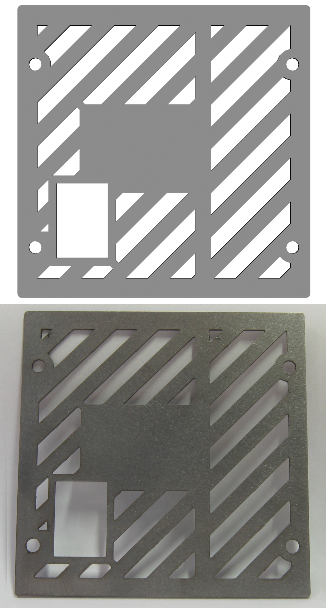

The slot the cutter still takes after the path is moved
A saw, a laser, a plasma arc, and a waterjet all leave a gap: a toothed blade, a beam, an arc, or a slurry leaving a mixing tube. That gap is the loss this article is counting. Compensation does not close it. It only chooses which side of the drawn line loses the stock.
On an outside profile the finished part sits inside the cut. If the cutter runs on the line, half the slot comes out of the part, so the piece is small. Compensation stands the cutter off into the skeleton so the near edge of the slot lands on the drawing. On an inside profile, running on the line enlarges the opening; compensation stands the cutter off into the slug instead. The skeleton, the slug, the blade or nozzle, and the sheet edge are what you can point to on the table.
OMAX’s ProtoMAX tool-path help draws that split: one line for the part perimeter in LAYOUT, and a thicker line for the path that already includes the tool offset, because the abrasive jet wears material away as it machines (opened 29 September 2026). That second line is the cutter. It is not a new outline of the part.
Decision: treat every closed path as either an outside or an inside profile before the nest runs. A hole offset the same way as the outer contour will be the wrong size even when the outer contour is right.

Why moving the cutter is not the same as changing the programmed size
How a kerf allowance changes the size you program is about editing the geometry itself. That is a different failure. If you enlarge or shrink the CAD so the slot is already in the drawing, and you also apply compensation on the machine, the slot is counted twice. The part then misses the drawing by about one full kerf, not half. Compensation leaves the drawing alone. A kerf allowance in CAD changes the drawing. Pick one.
A catalog width fails in a third way. Diablo lists item D0724X3, a 7-1/4 in 24-tooth ATB framing blade, with a kerf of 0.059 in and a plate of 0.040 in (opened 29 September 2026). That 0.059 in is the maker’s tooth-set figure for that blade, not a measured slot in named plywood on a named saw, and not an offset for a laser or a waterjet. After a blade change, the old measured slot is no longer the slot.
OMAX’s ProtoMAX page lists a mixing tube 2.25 in long with a 0.030 in internal diameter and a 0.008 in orifice (opened 29 September 2026). The 0.030 in bore is the consumable. GlobalMAX’s measuring-kerf help, a different OMAX line, states that abrasive-jet kerf can range from 0.021 in to 0.060 in depending on nozzle, thickness, and mixing-tube wear, and that the offset should equal half the kerf width (opened 29 September 2026). Do not copy one machine’s catalog bore onto the other machine’s offset.
Decision: if the only number you have is a blade listing or a mixing-tube bore, leave the compensation width blank until a coupon from this stock, this thickness, this process, and this machine has been measured.

What to read on the spec, the coupon, and the first part
Open the maker page for the cutter you are running, and write the date. For the waterjet offset rule used here, that page is OMAX GlobalMAX “Measuring Kerf,” opened 29 September 2026. It states that the offset should equal half the kerf; too small an offset lets a fatter jet cut extra material from the part; too large an offset leaves extra material, especially at leads. Their worked example uses a 0.40 in kerf and a 0.20 in offset to show the half-width arithmetic. That example is much larger than the 0.021 in to 0.060 in range they list for the jet itself, so treat it as the arithmetic, not as a typical slot.
The same page says to measure kerf on a test part cut at the same quality and in the same material as the job, and that a slower nozzle tends to leave a wider slot. Mixing-tube wear can widen the slot and make the stream elliptical, so the offset is no longer the same in every direction. Record material, thickness, process, and machine next to the width. If one of the four is missing, the width stays blank.
On the first production part, use a caliper on an outside width or length, then on an opening. Do not use a stock edge the cutter never touched. If the outside is small and the hole is large, compensation was likely omitted. If both miss by about a full kerf, the drawing was probably already padded and the machine offset it again.
Decision: do not release the nest until those two caliper checks match the drawing within the job tolerance.
The decision before the nest, the quote, or the batch
This topic turns on one choice: move the cutter, or change the drawing, never both, and only after a coupon from this job. If the four facts are not known, leave the compensation width blank. A prototype that looked right without a recorded offset is not a setting for a production run. When the mixing tube, blade, or nozzle changes, the old coupon is retired.
Compensation does not buy the extra stock a later bend or machining pass still needs. That allowance belongs on the blank. A press-fit or joint clearance is a second number after the slot exists; it is not the kerf offset. OMAX says that if you need more than one offset, for example clearance in one feature and a press-fit in another, you redraw those features rather than asking a single tool offset to stand in for both (opened 29 September 2026).
Decision: one measured slot, applied once as an offset, then a first-part caliper check. Anything else belongs on a different line of the quote.
Plasma travel is not the offset
Hypertherm’s CNC plasma quality notes put the squarest cut face on the right of the torch as it travels. An outside contour is therefore run so that good edge stays on the part; a hole is run the other way so the same rule still holds (opened 29 September 2026). That is travel direction. It does not set how far the torch stands off the drawing. You still need a kerf offset so the slot sits in the waste of each of those paths.
The same maker’s HPR130XD specification lists cut angle in ISO 9013 range 2–4, and states that a lower range means a smaller angle on the cut face (opened 29 September 2026). Compensation will not square a bevel the process already left. Do not treat a cut-angle range as a kerf width.
Keep the ProtoMAX mixing-tube diameter of 0.030 in next to that machine. Keep the GlobalMAX kerf range of 0.021 in to 0.060 in next to that documentation. A useful record names material, thickness, process, and machine.
Decision: write the offset beside the coupon that produced it. If the coupon and the job do not share all four facts, do not use the number.
The mistake that makes the first part the wrong size
The harmful action is applying kerf twice, or not at all, and then reading the drawing as if it were a report of the cut. Operators pad the CAD, turn on compensation, and cut a batch that is small on the outside and large on the inside. Estimators quote the drawn size while the machine still runs on the line, so every outside part is short by about one slot. Either error wastes the sheet you already bought. Check the first part with a caliper, on an outside profile and on an opening, before the rest of the nest is treated as finished goods.
Read next: What a kerf width is actually measuring. How a press-fit or a joint clearance differs from kerf compensation.