How a kerf allowance changes the size you program
A kerf allowance moves the toolpath off the finished edge. Measure the slot on a coupon before you type an offset for the batch.
A kerf allowance is the offset that moves the cutter to one side of the finished edge. If the beam, jet, or blade runs down the middle of a drawn line, each outside profile on sheet metal, plywood, acrylic, or stone finishes small by about half the slot, and each hole finishes large by the same amount. Measure that slot on a coupon from this stock, this thickness, and this machine before the offset is typed for the batch or the quote.
Answer box
What is being counted: The programmed offset that places the edge of the slot on the finished size, not the centre of the cutter.
What is not being counted: The finished size on the drawing, a later bend allowance, or the tightness of a joint after the slot is already cut.
The measurement that decides it: The slot width on a coupon cut in the same material, thickness, process, and machine, taken at the widest point of that slot.
What a catalog figure leaves out: The 0.126 in kerf listed for a Freud P410 10-inch general-purpose blade is the maker’s figure for that blade. It is not the slot that blade will leave in a given plywood thickness on a given saw, and it is not a laser or waterjet offset.
Check before the batch or the quote: Caliper the outside of a coupon part and the inside of a coupon hole. If the outside is small and the hole is large, the path is still running through the middle of the slot.
Last checked: 29 September 2026
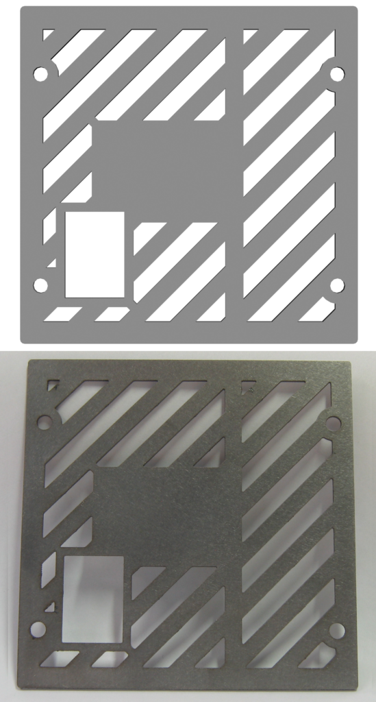

Where the slot sits on an outside edge and inside a hole
The cutter does not travel as a line. A toothed blade takes a strip as wide as the teeth can clear. A focused laser melts or vaporizes a gap that is barely wider than the beam. An abrasive waterjet erodes a slot that starts at the mixing tube and then widens as that tube wears. A plasma arc burns a wider join than a laser. In every case the missing strip is the kerf. The finished part is whatever stock is left after that strip is gone.
On an outside profile the slot eats inward from the drawn line. The part comes out smaller than the drawing unless the path is shifted outward so that the inner face of the slot lands on the required edge. On an inside profile — a hole, a window, a slot in the part — the cutter sits inside the opening. The slot eats outward. The opening comes out larger than the drawing unless the path is shifted inward so that the outer face of the slot lands on the required edge. The drawing stays the same. The allowance moves the toolpath. It does not redraw the part.
A saw cutoff between two lengths of bar or extrusion is the same idea in one dimension: the blade takes a length, so each finished piece is shorter than the programmed stop unless that stop already includes the slot. Sheet nesting has the same loss between neighbouring parts. The number typed into the program is still not the size on the drawing. It is the distance the centre of the cutter must keep from the finished edge.
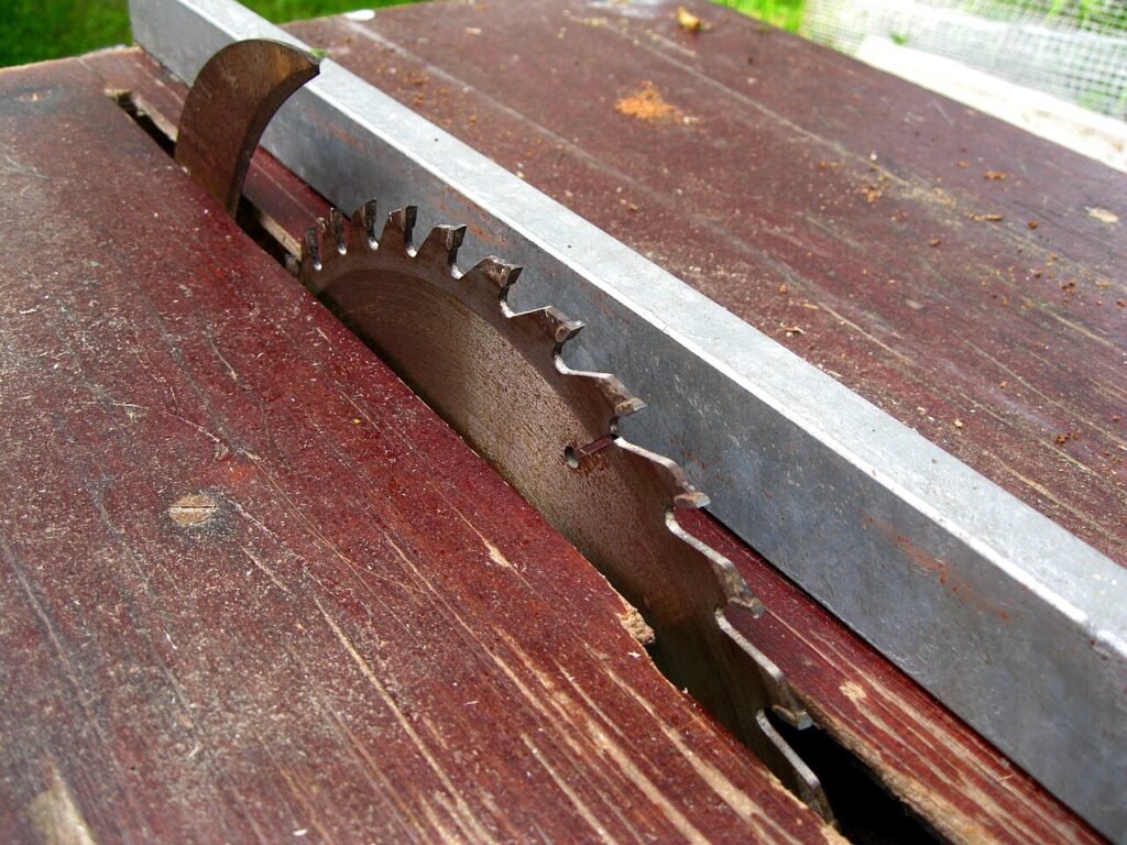

Why a catalog kerf is not the number in the program
A catalog width and a measured coupon fail in different ways. The catalog tells you what the maker prints for that consumable. Freud’s current listing for the P410, opened on 29 September 2026, states a 10-inch diameter, 40 teeth, a 0.126 in kerf, and a 0.098 in plate, for wood, laminate, veneered plywood, hardwoods, and melamine on a table saw, miter saw, or radial-arm saw. That 0.126 in figure is the maker’s kerf for that blade under the listing. It is not a measurement of the slot left in a particular sheet on a particular saw after the blade has been used, resharpened, or run in a different thickness. Copying 0.126 in into a laser nest or a waterjet material table treats a wood-blade listing as if it were a programmed offset for another process. It is not.
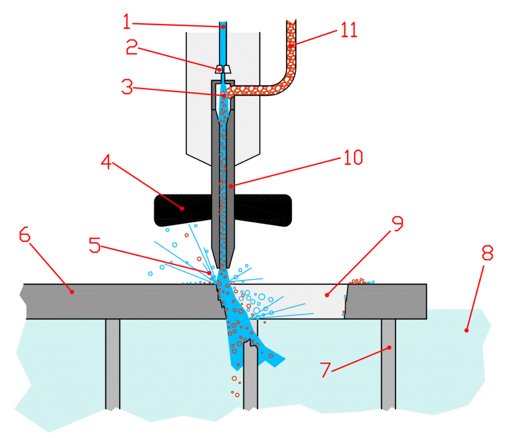
The coupon is the other measurement. It is a test cut in the same material, thickness, and machine as the job. The slot you caliper on that coupon is the loss the program has to allow for. A maker page for a waterjet, opened the same day, states that the abrasivejet kerf can range from 0.021 in to 0.060 in depending on the nozzle, the thickness being cut, and wear on the mixing tube, and that the kerf is typically measured at its widest point. That range is the maker’s envelope for that process. It is not a single offset to paste onto a saw, a laser, or a plasma table. Thickness changes the slot even when the material name stays the same. After a blade, nozzle, or mixing tube change, the old measured kerf is no longer the slot.
What to check on the spec sheet and the coupon
Open the current specification for the blade, nozzle, or machine you actually run, and write the date. On the Freud P410 page the figure to record is the listed kerf of 0.126 in, next to the blade identity, not next to a laser head. On TRUMPF’s laser-cutting application page, opened 29 September 2026, the maker states that the kerf is barely wider than the focused laser beam and that the focal diameter determines the gap width and the form of the kerf. That page does not give one millimetre to type into every laser program. On TRUMPF’s technology comparison, opened the same day, the maker states a laser kerf of less than 0.5 mm and a plasma kerf of 1 mm to 4 mm. Those two figures sit on one table so that nobody treats them as the same allowance.
On the coupon, cut a simple outside square and a simple inside hole in the job material and thickness, at the same quality or feed the batch will use. Measure the outside with a caliper. Measure the hole. If you programmed the drawing size with no offset, the outside will be small by about half the slot on each side and the hole will be large by about half the slot on each side. Record the material, the thickness, the process, and the machine next to the measured slot. If one of those four is missing, the width stays blank. A catalog line, a product photo, or a number copied from another shop is not that record.
ISO 9013:2017, confirmed in 2022 and opened on 29 September 2026, classifies thermal cuts for laser from 0.5 mm to 32 mm, plasma from 0.5 mm to 150 mm, and flame from 3 mm to 300 mm. That is the thickness range the standard covers. It is not a kerf-allowance table. Do not type a quality class from that standard into a CAM offset field as if it were a slot width.
What to type, and when to leave the field blank
The decision this topic turns on is whether the offset field is filled from a coupon or left blank. Fill it only when the material, the thickness, the process, and the machine are all known and the slot has been measured on a coupon from that combination. Then the program can shift an outside path away from the part and an inside path into the opening by half of that measured slot, or by whatever that controller stores as a tool offset derived from that slot. Leave the field blank when any of the four facts is missing. Do not borrow a laser figure for a saw nest. Do not keep last month’s waterjet offset after the mixing tube has been changed.
If the first article of a batch is already off, the coupon has already spoken. A part that is too small on the outside, or a hole that is too small, tells you the path is too close to the finished edge. A part that is too large, or a hole that is too large, tells you the path is too far away. Adjust the allowance from that measurement. Do not adjust the drawing to hide a wrong offset. The drawing is the finished size. The allowance is the path.
Half a measured slot is still only for that jet
OMAX’s ProtoMAX knowledge-base page on measuring the abrasivejet kerf, opened 29 September 2026, states that the tool offset entered in the material setup should always be equal to half the kerf width. It also states that an offset that is too small lets the fatter kerf cut extra material away from the part, and an offset that is too large leaves extra material on the part. That half-slot rule is the maker’s instruction for that waterjet software, tied to a kerf measured at the widest point, on a test part cut with the same quality and material as the job. It is not a universal millimetre for every machine in the shop. A plasma join of 1 mm to 4 mm on the TRUMPF comparison page is several times a laser kerf of less than 0.5 mm. Typing 0.126 in from the P410 blade listing into either of those thermal processes would move the path by a wood-saw catalog figure that those processes do not use.
The mixing tube on a waterjet is one of the parts you can point to when the old offset stops matching. Wear widens the stream and can make it elliptical, so the slot is no longer the same in every direction. The coupon has to be cut again. The drawing does not change. The allowance does.

The mistake that ships undersize parts
The harmful mistake is to type one offset onto every cutter, or to treat a catalog kerf as the finished size. A path that follows the drawing line without an allowance makes every outside part small and every hole large. A path that uses a borrowed millimetre from another machine, another thickness, or another process makes the error look like a random tolerance problem when it is still the slot sitting on the wrong side of the edge. Check the first part with a caliper. If the outside and the hole disagree in opposite directions, the allowance is wrong. Do not release the nest, the quote, or the batch on a number that was never measured on this stock, this thickness, this process, and this machine.
Read next: What a kerf width is actually measuring · What a test coupon is for before a kerf number is used on a batch